
Thursday, 23 October 2014
Security System Switcher
An audio signal can be used as a form of input to control any security system. For example, an automatic security camera can be configured to respond to a knock on the door. The circuit described here allows the security system to automatic in on state. It uses a transducer to detect intruders and a 5V regulated DC power supply provides power to the circuit.
As shown in Fig. 1, a condenser microphone is connected to the input of small signal Pre- amplifier built around transistor T1. Biasing resistor R1 determines to a large extent the microphone sensitivity. A microphone usually has an internal FET which requires a bias voltage to operate. The sound picked up by the microphone is amplified and fed to input pin 2 of IC1 (LMC555) wired in monostable configuration.
As shown in Fig. 1, a condenser microphone is connected to the input of small signal Pre- amplifier built around transistor T1. Biasing resistor R1 determines to a large extent the microphone sensitivity. A microphone usually has an internal FET which requires a bias voltage to operate. The sound picked up by the microphone is amplified and fed to input pin 2 of IC1 (LMC555) wired in monostable configuration.

Fig. 1: Security system switcher
IC2 (CD4538B) is a dual, precision monostable multivibrator with independent trigger and reset controls. The output of IC1 is connected to the first trigger input pin 4 of IC2(A) through switch S1. If an intruder opens or breaks the door, IC1 is triggered by sound signals; the timer output pin 3 of IC1 goes high and enables first monostable multivibrator IC2(A). IC2(A) provides a time period of around 5 to 125 seconds, which is adjusted with preset VR1.
Another monostable multivibrator IC2(B) also provides a time period of around 25 to 600 seconds, which is adjusted with preset VR2. The output of IC2(B) is used to energise relay RL1. Indicator LED1 is provided to display the relay activity. Any AC/DC operated security gadget is activated or deactivated through a security switch. Thus, the security switch of the gadget is connected in the n/o contacts of the relay.You can also operate high power beacons, sirens or hooters in place of the security switch for any AC/DC operated security gadget.
Assemble the circuit on a general-purpose PCB and enclose it in a cabinet as shown in Fig. 2 along with 5V adaptor for powering the circuit. Connect the security switch according to the circuit diagram and use appropriate AC/DC power supply required to operate the security gadget.

Fig. 2: Proposed cabinet
Warning! All relevant electrical safety precautions should be taken when connecting mains power supply to the relay contacts. With the help of single pole double throw (SPDT) switch S1, internal or external trigger input (active high signal) can be selected.
Water Pump Controller

A water pump controller senses the level of water in a tank and drives the water pump. The circuit described here is built around timer IC1 (555). When the water level of tank goes below the low level marked by 'L' the voltage at pin 2 of IC1 becomes low. As a result, internal SR-flip-flop of IC1 resets and its output goes high. This high output pin 3 of IC1 drives relay driver transistor T1 (BC547) and energises relay RL1. Water pump gets mains power supply through n/o contacts of the relay and is powered on. It starts filling water in the tank.
When the water level goes high and reaches the high level marked by 'H', the voltage at pin 6 of IC1 also goes high. As a result, internal SR-flip-flop of IC1 sets and its output goes low. This low output pin 3 of IC1 cuts off relay driver transistor T1 and de-energises relay RL1. Water pump disconnects from the mains power supply through n/c contacts of relay and goes off. This stops the water flow.
Use 12V battery or 12V adaptor to operate the circuit. Assemble the circuit on a general-purpose PCB and enclose in a suitable cabinet. Use three-sensor (thick conductive wire) and fit into the tank ensuring that 12V sensor touches the bottom and low-level sensor remains just above the bottom. High level sensor should be placed at a height till where the water needs to be filled. The circuit is economical, highly reliable and can be easily constructed.

Battery-Low Indicator

Battery-Low Indicator
Rechargeable batteries should not be discharged below a certain voltage level. This lower voltage limit depends upon the type of the battery. This simple circuit can be used for 12V batteries to give an indication of the battery voltage falling below the preset value. The indication is in the form of a flickering LED.
At the heart of the circuit is voltage comparator IC LM319 (IC1). It is a dual comparator with a TTL-compatible output. We have used only one comparator here. A reference voltage of 1.2 volts generated by band-gap reference diode D1 (LM385) is applied to the non-inverting input (pin 4) of the comparator. The inverting input (pin 5) of the comparator is fed a voltage generated from the potential divider arrangement built around resistors R2 and R3 and preset VR1. That means, if you are using a 12V battery and want an indication as soon as the battery voltage goes below 10.5V, adjust the voltage at the inverting input using reset VR1 so as to get a voltage of 1.2 volts (with battery voltage at 10.5V).
Initially, when the battery is fully charged, the voltage at the inverting input of IC1 is higher than the non-inverting input and output pin 12 of IC1 remains low. The reset pin (pin 4) of IC2 connected to pin 12 of IC1 also remains low and the astable multivibrator built around IC2 does not oscillate. As a result, LED1 does not flicker.
When the battery voltage falls below 10.5V, the voltage at the inverting input of IC1 becomes lower than the non-inverting input and the output of IC1 goes high. The reset pin of IC2 connected to pin 12 of IC1 also goes high and the astable multivibrator built around IC2 starts oscillating. LED1 flickers to indicate that the battery voltage is low and the battery needs to be charged before further use. Both IC1 and IC2 operate off regulated +5V DC generated by voltage regulator IC 7805 (IC3).
Assemble the circuit on a general-purpose PCB and enclose in a suitable cabinet. Mount LED1 and switch S1 on the front side of the case. Connect a 12V battery to check its voltage level.
Over-Speed Indicator

A 12V DC motor (M1) is coupled to the rotating part of the appliance with a suitable fixing arrangement. When the motor rotates, it develops a voltage.
This over-speed indicator is built around operational amplifier CA3140 (IC1). Set the reference voltage (depending on the desired speed) by adjusting preset VR1 at pin 2 of IC1. When the voltage developed at pin 3 of IC1 is higher than the reference voltage at pin 2, output pin 6 of comparator IC1 goes high to sound piezobuzzer PZ1 and light up LED3.
The rotation indicator circuit is built around AND gate 74LS08 (IC2). Pin 2 of gate N1 goes high when the motor rotates in forward direction, while pin 1 of gate N1 is pulled high via resistor R2. When both pins 1 and 2 are high, output pin 3 of gate N1 goes high to light up LED1. Similarly, pin 5 of gate N2 goes high when the motor rotates in reverse direction. When both pins 4 and 5 are high, output pin 6 of gate N2 goes high to light up LED2
.
Simple Stereo Level Indicator

Usually, low-priced home stereo power amplifiers don’t have output level indicators. An output power level indicator can be added to each channel of these stereo power amplifiers. As low levels of the output power are not disturbing and damaging to the people, there is no need to add a preamplifier and low-level detector before IC LM3915. But you should know when the output power becomes considerably high.
Here we present a very simple, low-cost stereo-level indicator circuit for home power amplifiers with power rating of around 0.5W. The circuit is built around two LM3915 dot/bar display driver ICs (IC1 and IC2). LM3915 senses analogue voltage levels to drive ten LEDs, providing a logarithmic 3dB/step analogue display.
The voltage levels below 1V are not important because these correspond to a low level of the audio signal. Similarly, input voltage levels above 30V correspond to too high levels of the output power, which are not applicable for home power amplifiers. So the voltage levels of our interest are 1V to 30V, which can be handled directly with LM3915. LM3915 needs no protection against ±35V inputs, which simplifies the circuit.
Most audio power amplifiers can drive 2-ohm to around 32-ohm loads. A load of several kilo-ohms will not change the conditions for the amplifier. CON1 is the input connector and CON2 output connector for the loudspeaker or headphone. Each channel has its own LM3915 and ten LEDs to indicate the power level. To indicate the different audio levels, select LEDs of three colours as per your liking. For example, you can have five green LEDs, three yellow LEDs and two red LEDs.
If appropriate signal generators and measuring equipment are not available, the level indicator can be calibrated based on personal observations. For example, the audio signal should be in the green LEDs zone when the signal is strong enough but not irritating, in the yellow zone when it is disturbing or starting to get distorted, and in the red zone when it is heavily distorted or too strong to listen to in the room.
Calibration can be done with the help of potentiometers VR1 and VR2, which are optional. Switches S1 and S2 let you select between two modes of LM3915 operation—the bar mode and the dot mode. These too can be removed or replaced with jumpers, if not required. When the switches are removed, leave pins 9 of IC1 and IC2 open.
The circuit works off regulated 12V. You can also power it through a 12V rechargeable battery.
Assemble the circuit on a general-purpose PCB and enclose in a suitable cabinet. Fix all the LEDs in two rows on the front side of the cabinet. Also affix the two terminals for input and output on rear side of the cabinet
.
Water level indicator

Here’s a simple water-level indicator for overhead tanks that uses three LEDs (LED1, LED2, and LED3) to indicate minimum, middle, and maximum water levels in the tank.
The sensor probes comprise A, B, C, and D, where A is the common probe and B, C, and D are meant for sensing the minimum, middle, and maximum levels, respectively. When water in the tank touches sensor wires A and B both, a small current passes from A to B through water and to the base of transistor T1 via resistor R1. As a result, transistor T1 conducts, causing LED1 to glow. Similarly, when water touches sensor C, LED2 glows to indicate that the water has reached the middle level. Finally, when water touches sensor D, LED3 glows to indicate the maximum level of water. Thus all the three LEDs glow when the tank is full. At this stage, the motor should be switched off manually.
The sensor probes should be kept in the tank vertically and connected to the main circuit using four flexible PVC wires of different colours.
The circuit is powered by a battery eliminator or a 6V battery and kept near the motor switchboard. The current drawn by the circuit, when all the LEDs glow, is up to 50 mA, which is less than the current drawn by a 6V bed-lamp.
Power Supply Rectification
Basic Power Supply Rectification Tutorial
Many devices, in particular electronics, must use DC or direct current. A diode is a solid-state device that conducts in one direction only. When the anode (A) is positive and the cathode (K) is negative (though the load) current (I'm assuming electron flow from negative to positive) will flow through the load, through the diode and back to the power supply.
Thus current will flow only of the positive half-cycle (0 to 180 degrees) and the diode will shut-off during the negative half-cycle from 180 degrees to 360 degrees. The period of a sine wave from 0 degrees to 360 degrees equals 1/F. In the case of 60 Hertz it's 1/60 = 16.7 mSec.

What is power? Voltage (in volts) is the "push" and the current (in Amperes) is what is being pushed. (Electric charges) Power is voltage times current. Power is measured in watts. So one amp at one volt equals one watt. (I'm not going into all of Ohm's Law here. See your text.) We must have voltage and current together to get power, so an open switch, broken wire, or a shut-off diode delivers no power.
In the case above, we get very poor power transfer with the diode off during the negative half-cycle and the positive half-cycle changing constantly between zero volts and peak. Note that Vmax is peak.
Figure 2
Let's say the AC in is 12.6 volts RMS. To get peak we multiply 12.6 by 1.414, which equals about 17.8 volts. But the average (or measured) voltage DC is peak times .3185 equals about 5.67 volts. This is what is called pulsating DC. Pure DC, such as from a 12 volt auto battery, has none of the "ripple" and will be a real 12 volts.
Put a DC voltmeter across the load above in figure 1, one will read about 5.66 volts. Switch the meter to AC, one will still read a voltage of some value. This is normal as one is reading the "ripple" riding the unfiltered raw D.C. Connect the same AC voltmeter across a clean DC source such as a car battery, one will read zero volts AC.
In figure 2 we inserted a capacitor across the load. The capacitor charges during the positive half-cycle, then discharges through the load during the negative half-cycle when we have no output. The amount of ripple is dependant on the resistance of the load and the size of the capacitor.
A larger capacitor produces less ripple or a higher resistance load (drawing less current thus less time for the capacitor to discharge) will reduce the level of ripple because the capacitor has less time to discharge. With no load at all, just the capacitor and the rectifier, the capacitor will charge to peak.
A word of caution. If constructing these circuits observe capacitor polarity and diode polarity. The voltage ratings of the capacitors should exceed the expected peak voltage by 50%. Also note the current ratings of the transformers and diodes.
Figure 3
Full-wave rectification
Full-wave rectification converts both polarities of the input waveform to DC (direct current), and is more efficient. However, in a circuit with a non-center tapped transformer, four diodes are required instead of the one needed for half-wave rectification. This is due to each output polarity requiring two rectifiers each. Four rectifiers arranged this way are called a diode bridge or bridge rectifier.
Note that in this example the arrows show conventional current flow, not electron flow I use with my students. This causes endless confusion for students as the military, etc. use electron flow in their training material while semiconductor classes use conventional current. Just be aware of this as one follows this material. Electron flow is from negative to positive, conventional (or charge) flow is from positive to negative.
In figure 3 D1 and D2 conduct during the positive half-cycle while D3 and D4 conduct during the negative half-cycle. Power delivered here is twice that of half-wave rectification because we are using both half-cycles. Using 12 volts AC again, we have 12.6 X 1.414 or 17 volts peak. (17.8 volts) But now to get the average we multiply by peak (17.8 volts) by 0.637 which equals 10.83 volts, double that of half-wave.
In addition we can use a smaller filter capacitor to clean out the ripple than we used with half-wave rectification. We have also doubled the frequency from 60 Hertz to 120 Hertz. It should be noted that when this circuit is constructed the voltage on the meter will be about one volt low. This is due to a 0.6 volt drop across the diodes, meter calibration due to frequency change (from 60 Hz to 120 Hz), and calculation errors.
Figure 4 typical bridge rectifiers.

Figure 5
Figure 5 above illustrates another method to obtain full-wave rectification. In this case we use a center-tapped transformer and two diodes. In using the center-tap (C) as a common, the voltage A and B is 180 degrees out of phase. When A is positive, D1 will be forward biased and conduct, while B will be negative thus reverse-biasing D2, while is non-conductive. On the negative half cycle in relation to A when D1 doesn't conduct, D2 will conduct.
It should be noted the output voltage will be cut by half. If we use a 25.2 volt, three amp transformer, the output voltage will be 12.6 volts. There is some controversy on output current. We are dealing RMS amps and have to factor in transformer impedance. (Z) During each half-cycle in this configuration current flow in one-half the total windings. Based on resistance of the wire, Z, etc. the current can be 1.2 to 1.8 times the rated current. I'd urge caution on these claims and wouldn't go above 1.4. All of the previous rules for peak, output voltage, etc. still hold true.
How to connect batteries in Series-Parallel

How to connect batteries in Series-Parallel
This is an introduction to how to properly connect batteries and cells in series or parallel for greater voltage or current. I'll begin with an explanation of terms, then examples, then experiments. I will only deal here with direct current (DC) devices only. This page has been updated September 2, 2011.
Terms: a cell is an individual electric generator. This can be a flashlight cell such as AAA, AA, C, or D cells, or solar cells or even thermal couples. A battery is a group of two or more cells. They are connected in series positive (+) to negative (-) for greater voltage, or in parallel (+ to + and - to -) for greater current capacity.

The individual cells inside a 9-volt battery.
An everyday examples of a battery is the 9-volt transistor battery, which is six 1.5-volt cells in series. The common automobile battery consists of six 2.1-volt lead-acid cells in series. With a battery of these types that are sealed the failure of a single cell ruins the whole battery.
All batteries consist of individual cells. There are two broad categories of cells:
Primary cells are used once and when discharged are thrown away. Common carbon-zinc and Alkaline are examples of this. There have been attempts to recharge these types of batteries, I wouldn't try this because they could explode or leak.
Secondary cells can be recharged by applying a slightly higher voltage (+ to + and - to - ) to the unit. While a typical auto battery fully charged will read a little over 12.6 volts, the charging system operates at 13-14 volts. Measuring this voltage while the vehicle is idling is a good way to test the charging system.
Examples of these type cells are nickel-cadmium (NiCd), lithium-ion used in many laptop computers, and lead-acid. If these are over charged this can damage the cells and could lead to spewing or explosion.
Examples of these type cells are nickel-cadmium (NiCd), lithium-ion used in many laptop computers, and lead-acid. If these are over charged this can damage the cells and could lead to spewing or explosion.
Power Considerations
The output voltage of any cell be it chemical, photovoltaic, or thermal is dependant on the materials that make up the cell. So a carbon-zinc cell will produce 1.5 volts regardless of size. It can be a AAA or the size of a truck, it's still 1.5 volts. The size does play into capacity or the amount of current the cell can deliver.
"The more electrolyte and electrode material there is in the cell the greater the capacity of the cell. Thus, a small cell has less capacity than a larger cell, given the same chemistry (e.g., alkaline cells), though they develop the same open-circuit voltage." (Wiki) This is also known as ampere-hour (Ah) rating.
For example a 6-volt 4.5 Ah battery will produce 4.5-amperes of current for 1 hour or 1 ampere for 4.5 hours. This is true of either primary or secondary cells. All silicon solar cells produce about .5 volts, but the greater the physical area the greater the current capacity.

A working Example
Pictured above is a 225 watt solar panel made with 60 solar cells producing 30 volts at 7.5 amps. In this case we wired all 60 cells in series (.5 volts X 60) for a panel to be used with a 24-volt charging system. We could have wired the same panel for 15-volts for a 12-volt charging system by connecting two groups of 30 cells wired in series, then connecting the two groups in parallel producing 15 amps of current at 15 volts.
Note that these panels are designed to charge lead-acid batteries or an inverter to feed power to the power line. Power is a product of voltage times current, so one solar cell advertised on Ebay is a 3' x 6' poly crystalline solar cell that produces 3.6A or a total of 1.8 watts at .5 volts.
The cells used in the above panel are 6' x 6' and this 30 volt rating is at no load. Batteries be they solar or chemical always have higher open-circuit voltages than they do when being used. When testing any battery do it under load or with a voltmeter set for checking batteries. (It places a load on the battery internally.)
We must consider current in regards to what size wire we want to use. Higher current require a larger gauge thus more expensive wire.

Pictured above are the symbols for a single chemical cell and a single solar cell, a multi-cell battery, and multi-cell solar battery/panel.

Pictured above are cells in series. They are connected positive to negative and the voltages add while the current or Ampere-hour ratings stay the same. At this point each have become a battery. A battery can have any number of cells in series. Cells in series must be the same type and rating. We can connect a lower capacity cell into the string and get the voltages to add, but lower capacity will quickly discharge acting as a high resistance to the other cells dropping the output voltage.

Pictured above are the same cells in parallel. The output voltages stay the same but the current capacity adds. One can have any number of cells in parallel, but be sure they are the same type and voltage.
Pictured above are the symbols for batteries. The one on the right is my symbol for a solar battery or solar panel. For the following illustrations I will show the various ways to connect both solar and lead acid cells together. I'll assume the solar cells connected with thirty each in series in two separate panels producing 15 volts at 7.5 amps. I'll also assume four 6-volt lead acid batteries with a current rating of 40 Ah.
Note these need to be deep-cycle or marine batteries, not everyday car batteries.
Pictured above is a 24-volt solar charging system. I've wired my two 12-volt solar panels in series and the four 6 volt (actually 6.3) volt 40 Ah batteries in series, connected in parallel with the solar panels. This will produce about 24 volts at 40 amps for a total power of 960 watts for 1 hour from the four batteries. Or one can have 96 watts for 10 hours, etc.
We would use this to power a 24-volt inverter that converts DC to 120 volts AC for powering AC devices. One model rated at 400 watts is designed for powering solid state items such as computers, radios, etc. A compact fluorescent light rated at 20 watts would operate for over 48 hours even if no power was being delivered from the solar panels. In daylight power would come from both the batteries and panels. At the full 400 watts in this example the current would be 16.67 amps to the inverter from the battery bank.
We would use this to power a 24-volt inverter that converts DC to 120 volts AC for powering AC devices. One model rated at 400 watts is designed for powering solid state items such as computers, radios, etc. A compact fluorescent light rated at 20 watts would operate for over 48 hours even if no power was being delivered from the solar panels. In daylight power would come from both the batteries and panels. At the full 400 watts in this example the current would be 16.67 amps to the inverter from the battery bank.

Diode D1 acts as an electrical "check valve" allowing current to flow in only one direction. This keeps the batteries from discharging through the solar cells when the output voltage drops below the batteries at night. The arrow points to the N-type semiconductor material in the diode and is not the direction for current flow which is from negative to positive. Most websites on solar have this backwards.

Typical power inverter.
In fact this entire arrangement be copied then wired in parallel with each other. So four of these wired in parallel can deliver 160 amps at 24-volts or 3840 watts for one hour. To me this would be a better arrangement because we would use smaller gauge wire to the batteries and smaller blocking diodes saving money. This would also make each individual section more repairable without taking the whole system down.
Pictured above is one method to connect our four 6-volt 40 Ah batteries to two solar panels connected in parallel. The two panels can deliver a peak current of 15 amps. The capacity of the battery bank is now 12-volts at 80 amps. BAT1 and BAT2 are connected in parallel to each other as are BAT3 and BAT4 increasing the current rating to 80 Ah. The two pairs are then connected in series to produce 12 volts at 80 Ah for a total wattage of 960 watts.
Series batteries
PARTS AND MATERIALS
- Two 6-volt batteries
- One 9-volt battery
Actually, any size batteries will suffice for this experiment, but it is recommended to have at least two different voltages available to make it more interesting.
LEARNING OBJECTIVES
- How to connect batteries to obtain different voltage levels
SCHEMATIC DIAGRAM

ILLUSTRATION

INSTRUCTIONS
Connecting components in series means to connect them in-line with each other, so that there is but a single path for electrons to flow through them all.
If you connect batteries so that the positive of one connects to the negative of the other, you will find that their respective voltages add. Measure the voltage across each battery individually as they are connected, then measure the total voltage across them both, like this:
If you connect batteries so that the positive of one connects to the negative of the other, you will find that their respective voltages add. Measure the voltage across each battery individually as they are connected, then measure the total voltage across them both, like this:

Try connecting batteries of different sizes in series with each other, for instance a 6-volt battery with a 9-volt battery. What is the total voltage in this case? Try reversing the terminal connections of just one of these batteries, so that they are opposing each other like this:

How does the total voltage compare in this situation to the previous one with both batteries "aiding?" Note the polarity of the total voltage as indicated by the voltmeter indication and test probe orientation.
Remember, if the meter's digital indication is a positive number, the red probe is positive (+) and the black probe negative (-); if the indication is a negative number, the polarity is "backward" (red=negative, black=positive).
Analog meters simply will not read properly if reverse-connected, because the needle tries to move the wrong direction (left instead of right). Can you predict what the overall voltage polarity will be, knowing the polarities of the individual batteries and their respective strengths?
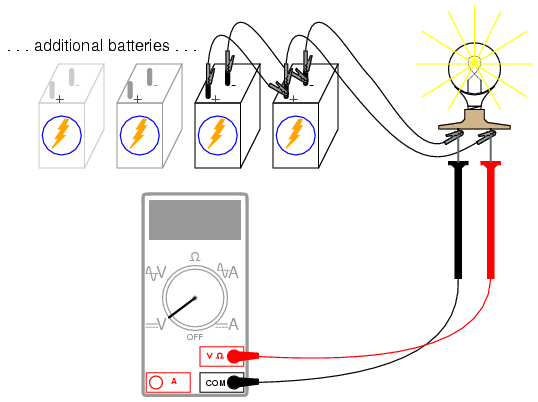
Parallel batteries
PARTS AND MATERIALS
- Four 6-volt batteries
- 12-volt light bulb, 25 or 50 watt
- Lamp socket
High-wattage 12-volt lamps may be purchased from recreational vehicle (RV) and boating supply stores. Common sizes are 25 watt and 50 watt. This lamp will be used as a "heavy" load for your batteries (heavyload = one that draws substantial current).
A regular household (120 volt) lamp socket will work just fine for these low-voltage "RV" lamps.
LEARNING OBJECTIVES
- Voltage source regulation
- Boosting current capacity through parallel connections

ILLUSTRATION

INSTRUCTIONS
Begin this experiment by connecting one 6-volt battery to the lamp. The lamp, designed to operate on 12 volts, should glow dimly when powered by the 6-volt battery. Use your voltmeter to read voltage across the lamp like this:

The voltmeter should register a voltage lower than the usual voltage of the battery. If you use your voltmeter to read the voltage directly at the battery terminals, you will measure a low voltage there as well. Why is this? The large current drawn by the high-power lamp causes the voltage at the battery terminals to "sag" or "droop," due to voltage dropped across resistance internal to the battery.
We may overcome this problem by connecting batteries in parallel with each other, so that each battery only has to supply a fraction of the total current demanded by the lamp. Parallel connections involve making all the positive (+) battery terminals electrically common to each other by connection through jumper wires, and all negative (-) terminals common to each other as well. Add one battery at a time in parallel, noting the lamp voltage with the addition of each new, parallel-connected battery:
There should also be a noticeable difference in light intensity as the voltage "sag" is improved.
Try measuring the current of one battery and comparing it to the total current (light bulb current). Shown here is the easiest way to measure single-battery current:

By breaking the circuit for just one battery, and inserting our ammeter within that break, we intercept the current of that one battery and are therefore able to measure it. Measuring total current involves a similar procedure: make a break somewhere in the path that total current must take, then insert the ammeter within than break:
Note the difference in current between the single-battery and total measurements.
To obtain maximum brightness from the light bulb, a series-parallel connection is required. Two 6-volt batteries connected series-aiding will provide 12 volts. Connecting two of these series-connected battery pairs in parallel improves their current-sourcing ability for minimum voltage sag:

Resistive Humidity Sensors
Resistive Humidity Sensors
Resistive humidity sensors measure the change in electrical impedance of a hygroscopic medium such as a conductive polymer, salt, or treated substrate. Photo 2. Resistive sensors are based on an interdigitated or bifilar winding. After deposition of a hydroscopic polymer coating, their resistance changes inversely with humidity. The Dunmore sensor (far right) is shown 1/3 size. |
The impedance change is typically an inverse exponential relationship to humidity
 Figure 2. The exponential response of the resistive sensor, plotted here at 25°C, is linearized by a signal conditioner for direct meter reading or process control. |
Resistive sensors usually consist of noble metal electrodes either deposited on a substrate by photoresist techniques or wire-wound electrodes on a plastic or glass cylinder. The substrate is coated with a salt or conductive polymer. When it is dissolved or suspended in a liquid binder it functions as a vehicle to evenly coat the sensor. Alternatively, the substrate may be treated with activating chemicals such as acid. The sensor absorbs the water vapor and ionic functional groups are dissociated, resulting in an increase in electrical conductivity. The response time for most resistive sensors ranges from 10 to 30 s for a 63% step change. The impedance range of typical resistive elements varies from 1000 ohms to 100,000,000 ohms.
Most resistive sensors use symmetrical AC excitation voltage with no DC bias to prevent polarization of the sensor. The resulting current flow is converted and rectified to a DC voltage signal for additional scaling, amplification, linearization, or A/DRconversion
 Figure 3. Resistive sensors exhibit a nonlinear response to changes in humidity. This response may be linearized by analog or digital methods. Typical variable resistance extends from a few kilohms to 100 MV. |
Nominal excitation frequency is from 30 Hz to 10 kHz.
The "resistive" sensor is not purely resistive in that capacitive effects makes the response an impedance measurement. A distinct advantage of resistive RH sensors is their interchangeability, usually within ±2% RH, which allows the electronic signal conditioning circuitry to be calibrated by a resistor at a fixed RH point. This eliminates the need for humidity calibration standards, so resistive humidity sensors are generally field replaceable. The accuracy of individual resistive humidity sensors may be confirmed by testing in an RH calibration chamber or by a computer-based DA system referenced to standardized humidity-controlled environment. Nominal operating temperature of resistive sensors ranges from -40°C to 100°C.
In residential and commercial environments, the life expectancy of these sensors is >>5 yr., but exposure to chemical vapors and other contaminants such as oil mist may lead to premature failure. Another drawback of some resistive sensors is their tendency to shift values when exposed to condensation if a water-soluble coating is used. Resistive humidity sensors have significant temperature dependencies when installed in an environment with large (>10°F) temperature fluctuations. Simultaneous temperature compensation is incorporated for accuracy. The small size, low cost, interchangeability, and long-term stability make these resistive sensors suitable for use in control and display products for industrial, commercial, and residential applications.
One of the first mass-produced humidity sensors was the Dunmore type, developed by NIST in the 1940s and still in use today. It consists of a dual winding of palladium wire on a plastic cylinder that is then coated with a mixture of polyvinyl alcohol (binder) and either lithium bromide or lithium chloride. Varying the concentration of LiBr or LiCl results in very high resolution sensors that cover humidity spans of 20%-40% RH. For very low RH control function in the 1%-2% RH range, accuracies of 0.1% can be achieved. Dunmore sensors are widely used in precision air conditioning controls to maintain the environment of computer rooms and as monitors for pressurized transmission lines, antennas, and waveguides used in telecommunications.
The latest development in resistive humidity sensors uses a ceramic coating to overcome limitations in environments where condensation occurs. The sensors consist of a ceramic substrate with noble metal electrodes deposited by a photoresist process. The substrate surface is coated with a conductive polymer/ceramic binder mixture, and the sensor is installed in a protective plastic housing with a dust filter.
The binding material is a ceramic powder suspended in liquid form. After the surface is coated and air dried, the sensors are heat treated. The process results in a clear non-water-soluble thick film coating that fully recovers from exposure to condensation (see Figure 4).
This document saved from http://www.sensorsmag.com/articles/0701/54/main.shtml
How to Test a Diac

How to Test a Diac
A diac is a two-electrode bidirectional avalanche diode which can be switched from off-state to the on-state for either polarity of the applied voltage. Again the terminal designations are arbitrary since the diac, like triac, is also a bilateral device. The switching from off-state to on-state is achieved by simply exceeding the avalanche break down voltage in either direction.
An unusual characteristic is once the Diac goes into conduction, the resistance drops rapidly sometimes called negative resistance. Stating this another way, "negative resistance characteristic, that is, voltage decreases with the increase in current."
Most DIACs have a three-layer structure with breakdown voltage around 30 V. DIACs have no gate electrode and are commonly used to trigger TRIACs. Some TRIACs contain a built-in DIAC in series with the TRIAC's "gate" terminal for this purpose.
DIACs are also called symmetrical trigger diodes due to the symmetry of their characteristic curve. Because DIACs are bidirectional devices, their terminals are labeled MT1 ("Main Terminal") and MT2. Ref. Wiki.
So much for theory, how does one check as DIAC? The only thing a volt-ohm meter will check is if the DIAC is shorted in the diode check mode. It will read "open" both ways otherwise. To really check a DIAC we need to apply a voltage and note where the DIAC conducts and turns off.
Fig. 2 variable power supply.
The Power Supply
The first thing we need is a variable D.C. power supply from 0-50 volts or more. In my industrial electricity class we do have a variable A.C power supply for 0-22 volts AC. If one is at home or has no access to a supply, one can be easily built.
Show above in Fig. 1 is a "home brew" test circuit. The "lamp dimmer" is simply a common dimmer circuit for room lighting available at any Lowe's or Home Depot. This should have a knob or slider control. This is used with a Radio Shack 120 to 24-volt transformer to form a variable A.C. supply. D1, D2, C1, C2 form a half-wave voltage doubler and filter. It wouldn't hurt to wire a 27k bleeder resistor across C1 and C2.
Perform the Test
If one has a 0-50 volt D.C. supply, all they need is U1 and R1. R1 is a 4.7k resistor.
Step 1: Set the voltage out to 0 volts as measured across TP1 and TP3. Connect a D.C. volt meter across TP2 (red lead) and TP3 (black lead). Slowly increase the voltage. In the case of my test, the DIACs' voltage appeared across R1 at about 30 volts on TP1 then quickly jumped up to between 10-15 volts. This is due to the fact a DIAC displays a negative resistance property once the breakover voltage is achieved the resistance will drop rapidly to some lower value. The voltage should steadily increase across R1 as the voltage from the supply is turned up. Don't go past 40-50 volts.
Step 2: Slowly turn the supply down and note the reading across R1. Between 15 and 25 volts in my case voltage suddenly dropped to zero.
Step 3: Reverse the DIAC, repeat steps 1 and 2. One should get the same results.
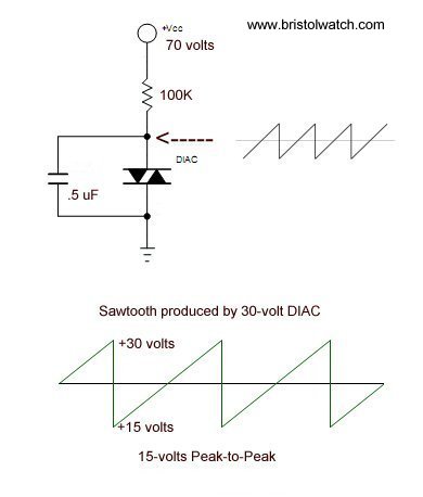
Fig. 3 DIAC connected as relaxation oscillator
A DIAC Sawtooth Oscillator
If one has an oscilloscope then we can connect the test DIAC to form a relaxation oscillator. In the circuit above the capacitor will charge through the 100k resistor. When the charge voltage reaches the DIAC breakover voltage the capacitor will quickly discharge through the DIAC until the voltage goes below the DIAC holding current, at which time the DIAC will turn off. At that point (around 15 volts) the capacitor will charge again and repeat the process.
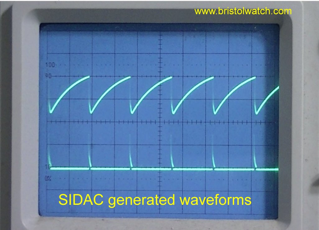
Fig. 4 Sawtooth waveform displayed on an oscilloscope.
In Fig. 4 is the actual waveform produced by a Diac relaxation oscillator. With the vertical set to 5 volts per division, our waveform has a P-P voltage of 15 volts.
The period (thus frequency) from beginning of charge to discharge is dependant on the value of the capacitor and charge resistor. Leaving the charge resistor at 100k and turning the power supply to 70-volts, the following for period (p) was measured:
C = .015uF: p = .275 mSec.
C = .100uF: p = 3 mSec.
C = .220uF: p = 6 mSec.
C = .330uF: p = 8.4 mSec.
C = .560uF: p = 15 mSec.
C = .100uF: p = 3 mSec.
C = .220uF: p = 6 mSec.
C = .330uF: p = 8.4 mSec.
C = .560uF: p = 15 mSec.
The frequency of the sawtooth waveform is found by taking the reciprocal of the period. Note the peak-to-peak voltage stayed the same value regardless of which capacitor I used.
How Diodes and Rectifiers Operate
How Diodes and Rectifiers Operate
A diode is an electrical device allowing current to move through it in one direction with far greater ease than in the other. The most common kind of diode in modern circuit design is the semiconductor diode, although other diode technologies exist. Semiconductor diodes are symbolized in schematic diagrams such as figures below. The term "diode" is customarily reserved for small signal devices. The term rectifieris used for power devices.
Semiconductor diode schematic symbol: Arrows indicate the direction of electron current flow.
When placed in a simple battery-lamp circuit, the diode will either allow or prevent current through the lamp, depending on the polarity of the applied voltage.
 Diode operation: (a) Current flow is permitted; the diode is forward biased. (b) Current flow is prohibited; the diode is reversed biased.
When the polarity of the battery is such that electrons are allowed to flow through the diode, the diode is said to be forward-biased. Conversely, when the battery is "backward" and the diode blocks current, thediode is said to be reverse-biased. A diode may be thought of as like a switch: "closed" when forward-biased and "open" when reverse-biased.
Oddly enough, the direction of the diode symbol's "arrowhead" points against the direction of electron flow. This is because the diode symbol was invented by engineers, who predominantly use conventional flow notation in their schematics, showing current as a flow of charge from the positive (+) side of the voltage source to the negative (-). This convention holds true for all semiconductor symbols possessing "arrowheads" the arrow points in the permitted direction of conventional flow, and against the permitted direction of electron flow.
Like check valves, diodes are voltage-operated devices. The essential difference between forward-bias and reverse-bias is the polarity of the voltage dropped across the diode. Let's take a closer look at the simple battery-diode-lamp circuit shown earlier, this time investigating voltage drops across the various components in figure below.

Diode circuit voltage measurements: (a) Forward biased. (b) Reverse biased.
A forward-biased diode conducts current and drops a small voltage across it, leaving most of the battery voltage dropped across the lamp. If the battery's polarity is reversed, the diode becomes reverse-biased, and drops all of the battery's voltage leaving none for the lamp. If we consider the diode to be a self-actuating switch (closed in the forward-bias mode and open in the reverse-bias mode), this behavior makes sense. The most substantial difference is that the diode drops a lot more voltage when conducting than the average mechanical switch (0.7 volts).
This forward-bias voltage drop exhibited by the diode is due to the action of the depletion region formed by the P-N junction under the influence of an applied voltage. If no voltage applied is across a semiconductor diode, a thin depletion region exists around the region of the P-N junction, preventing current flow. (Figure below (a)) The depletion region is almost devoid of available charge carriers, and acts as an insulator.

Diode representations: PN-junction model, schematic symbol, physical part.
The schematic symbol of the diode is shown in the figure above (b) such that the anode (pointing end) corresponds to the P-type semiconductor at (a). The cathode bar, non-pointing end, at (b) corresponds to the N-type material at (a). Also note that the cathode stripe on the physical part (c) corresponds to the cathode on the symbol.

If a reverse-biasing voltage is applied across the P-N junction, this depletion region expands, further resisting any current through it. (above)
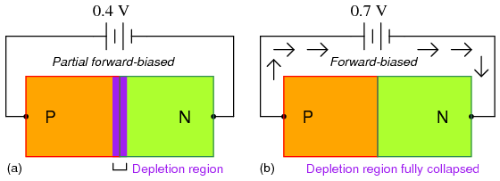
Increasing forward bias from (a) to (b) decreases depletion region thickness.
Conversely, if a forward-biasing voltage is applied across the P-N junction, the depletion region collapses becoming thinner. The diode becomes less resistive to current through it. In order for a sustained current to go through the diode; though, the depletion region must be fully collapsed by the applied voltage. This takes a certain minimum voltage to accomplish, called the forward voltage as illustrated above.
For silicon diodes, the typical forward voltage is 0.7 volts, nominal. For germanium diodes, the forward voltage is only 0.3 volts. The chemical constituency of the P-N junction comprising the diode accounts for its nominal forward voltage figure, which is why silicon and germanium diodes have such different forward voltages.
Forward voltage drop remains approximately constant for a wide range of diode currents, meaning that diode voltage drop is not like that of a resistor or even a normal (closed) switch. For most simplified circuit analysis, the voltage drop across a conducting diode may be considered constant at the nominal figure and not related to the amount of current.
Forward voltage drop remains approximately constant for a wide range of diode currents, meaning that diode voltage drop is not like that of a resistor or even a normal (closed) switch. For most simplified circuit analysis, the voltage drop across a conducting diode may be considered constant at the nominal figure and not related to the amount of current.
A reverse-biased diode prevents current from going through it, due to the expanded depletion region. In actuality, a very small amount of current can and does go through a reverse-biased diode, called theleakage current, but it can be ignored for most purposes. The ability of a diode to withstand reverse-bias voltages is limited, as it is for any insulator.
If the applied reverse-bias voltage becomes too great, the diode will experience a condition known asbreakdown, which is usually destructive. A diode's maximum reverse-bias voltage rating is known as thePeak Inverse Voltage, or PIV, and may be obtained from the manufacturer. Like forward voltage, the PIV rating of a diode varies with temperature, except that PIV increases with increased temperature anddecreases as the diode becomes cooler -- exactly opposite that of forward voltage.
If the applied reverse-bias voltage becomes too great, the diode will experience a condition known asbreakdown, which is usually destructive. A diode's maximum reverse-bias voltage rating is known as thePeak Inverse Voltage, or PIV, and may be obtained from the manufacturer. Like forward voltage, the PIV rating of a diode varies with temperature, except that PIV increases with increased temperature anddecreases as the diode becomes cooler -- exactly opposite that of forward voltage.
Typically, the PIV rating of a generic rectifier diode is at least 50 volts at room temperature. Diodes with PIV ratings in the many thousands of volts are available for modest prices.
- REVIEW:
- A diode is an electrical component acting as a one-way valve for current.
- When voltage is applied across a diode in such a way that the diode allows current, the diode is said to be forward-biased.
- When voltage is applied across a diode in such a way that the diode prohibits current, the diode is said to be reverse-biased.
- The voltage dropped across a conducting, forward-biased diode is called the forward voltage. Forward voltage for a diode varies only slightly for changes in forward current and temperature, and is fixed by the chemical composition of the P-N junction.
- Silicon diodes have a forward voltage of approximately 0.7 volts.
- Germanium diodes have a forward voltage of approximately 0.3 volts.
- The maximum reverse-bias voltage that a diode can withstand without "breaking down" is called thePeak Inverse Voltage, or PIV rating
Sunday, 19 October 2014
Battery Applications
The table below shows the range of applications which use batteries together with typical battery capacities required by the application. The section on Battery Types outlines the diverse range of batteries which are available for powering these applications.
| Type | Energy | Applications | ||
| Miniature Batteries | 100 mWh-2 Wh | Electric watches, calculators, implanted medical devices (Mostly Primary Cells in small Button Cell packages) | ||
| Batteries for Portable Equipment | 2 Wh-100 Wh | Flashlights, toys, power tools, portable radio and TV, mobile phones, camcorders, lap-top computers, memory refreshing, instruments, cordless devices, wireless peripherals, emergency beacons (Mostly Secondary Cells such as NiCad, NiMH andLithium Ion as well as some Alkaline primary cells) | ||
| SLI Batteries (Starting Lighting & Ignition) | 100-600 Wh | Cars, trucks, buses, lawn mowers, wheel chairs, robots (Mostly Lead Acid batteries) | ||
| Vehicle Traction Batteries | 20 -630 kWh | EVs, HEVs, PHEVs, fork lift trucks, milk floats, locomotives (NiMH and Lithium) | ||
| Stationary Batteries | 250 Wh-5 MWh | Emergency power, local energy storage,remote relay stations, communication base stations, uninterruptible power supplies (UPS). (Mostly Lead Acid with Lithiumrecently making some inroads) | ||
| Military & Aerospace | Wide range | Satellites, munitions, robots, emergency power, communications (Fuel Cells, Nickel Hydrogen, Water Activated batteries and other Alternatives) | ||
| Special Purpose | 3 MWh | Submarines (Mostly Lead Acid batteries) | ||
| Load Levelling Batteries | 5-100 MWh | Spinning reserve, peak shaving, load levelling (Various Lead Acid and Lithium plusAlternatives) | ||
Subscribe to:
Comments
(
Atom
)


